
SparkFun Produkt
Arduino and Breadboard Holder
76,00
DKK
Her finder du et bredt udvalg af Arduino produkter. Vi har alt fra selve Arduino boardet til forskellige Arduino shields, Arduino kits og Arduino tilbehør der giver dig mulighed for at udvide funktionaliteten og skabe mere avancerede Arduino projekter.
SparkFun Produkt

SparkFun Produkt

SparkFun Produkt
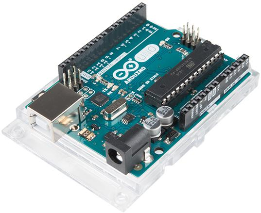
Arduino Boards: Udforsk vores udvalg af Arduino-boards, der fungerer som hjernen i dine projekter. Vi tilbyder forskellige varianter, herunder Arduino Uno Boards, Arduino Mega og Arduino Nano. Disse boards er nemme at bruge og understøttes af et stort fællesskab af Arduino-entusiaster, der deler deres Arduino projekter, viden og erfaringer.
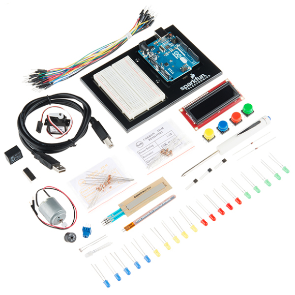
Arduino Kits: Vores Arduino-startersæt er perfekte til begyndere. De indeholder alt, hvad du har brug for for at komme i gang med Arduino-verdenen. Hvert kit leveres med et Arduino-board, komponenter som sensorer, motorer og LED'er, samt omfattende vejledninger og projekteksempler.
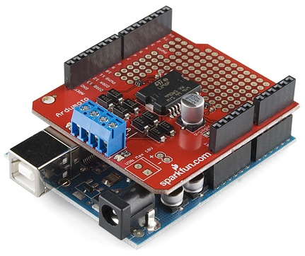
Arduino Shields: Opgrader dine Arduino-projekter med vores udvalg af Arduino-shields. Disse shields er specielt designede til at tilføje ekstra funktionalitet til dit Arduino-board. Uanset om du vil tilføje trådløs kommunikation, LCD-skærme eller motorstyring, har vi shields, der passer til dine behov.
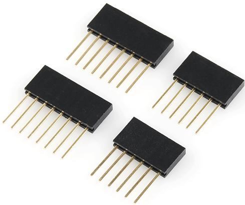
Arduino Tilbehør: Udforsk vores udvalg af Arduino-tilbehør, der omfatter moduler og kabler til programmere Arduino Boards, som er uden en USB to serial IC. Her ud over finder du produkter, som er specielt designet til at passe til Arduino hardwaren.
Uanset om du er nybegynder eller erfaren Arduino-entusiast, har vi de rette produkter til dig. Vores sortiment er nøje udvalgt for at sikre kvalitet og funktionalitet.
Udforsk vores underkategorier og find de nødvendige komponenter til at opbygge dine Arduino-projekter. Gør dig klar til at dykke ned i den spændende verden af elektronik og programmering med Arduino!
Arduino er en open-source elektronikplatform, der har revolutioneret måden, hvorpå vi skaber og interagerer med hardware. Siden sin introduktion i 2005 har Arduino gjort det nemt for kunstnere, designere, hobbyister og ingeniører at bringe deres ideer til live gennem interaktive projekter. Med en enkel hardware- og softwareopsætning kan brugere af alle færdighedsniveauer oprette komplekse elektroniske systemer og prototyper.
Arduino-platformen blev først introduceret i 2005, designet af et hold af italienske ingeniører med det formål at give studerende adgang til billige og brugervenlige værktøjer til deres elektronik- og programmeringsprojekter.
Historien om Arduino begynder i 2005 i Ivrea, Italien, hvor det blev skabt med det formål at tilbyde studerende en billig og nem måde at arbejde med elektronik.
Navnet "Arduino" kommer fra "Bar di Re Arduino", en bar i Ivrea, Italien, hvor nogle af platformens grundlæggere plejede at mødes.
Arduino boardene blev designet til at være fleksible og åbne, hvilket gjorde det nemt for brugere at tilpasse og dele deres kreationer. Dette åbne og samarbejdende miljø har ført til en eksplosion af innovation og har gjort Arduino til en central del af den moderne "maker-bevægelse".
I dag er Arduino blevet den de facto standard for hardwareprototyping og -udvikling. Det er blevet grundlaget for utallige projekter, lige fra hobbyniveau til professionelle applikationer. Arduino's enkelhed og tilgængelighed har gjort det til et naturligt valg for dem, der ønsker at eksperimentere med elektronik og skabe deres egne interaktive projekter.
Arduino bruges i et utal af forskellige projekter og applikationer. Alt fra enkle hobbyprojekter til komplekse videnskabelige instrumenter og kunstinstallationer. Arduino gør det let at integrere elektronik ind i interaktive projekter, hvilket gør det til et populært valg for kunstnere, designere, hobbyister og ingeniører over hele verden.
Med sin enkle og tilgængelige brugergrænseflade gør Arduino det nemt for alle, uanset erfaringsniveau, at komme i gang med elektroniske projekter. Arduino's open-source natur betyder, at der er et stort community af udviklere og entusiaster, der deler viden, vejledninger og kodeeksempler.
At komme i gang med Arduino kræver minimal opsætning, og der er en overflod af ressourcer tilgængelige online for at hjælpe nybegyndere. Arduino IDE (Integrated Development Environment) er brugervenlig og understøtter både Windows, Mac OS X og Linux.
Der er et væld af online ressourcer, herunder tutorials, vejledninger og projekteksampler, der kan hjælpe dig med at lære og mestre Arduino. Du kan besøge Arduino's officielle hjemmeside for at få adgang til disse materialer og deltage i Arduino-communityet.
Uanset om du er nybegynder eller en erfaren udvikler, er Arduino en fantastisk platform for at bringe dine ideer til live. Gennemse vores udvalg, find inspiration i communityet, og start dit næste projekt i dag. Vi er her for at støtte dig på din rejse med Arduino. Lad os bygge noget fantastisk sammen!